At one point or another, you’re inevitability going to run into the problem of not having enough pins on your Arduino to meet the requirements of your project or prototype. The solution to this problem? A shift register!
A shift register allows you to expand the number of pins you can use from your Arduino (or any micro controller for that matter) by using what is known as bit-shifting. If you have much experience with programming, there’s a good chance you have come across bit-shifting previously. For the purpose of this guide though, we’ll assume no prior knowledge.
In order to complete this guide you will need the following parts:
- An Arduino Uno
- A breadboard – I’d recommend two, as there will be a lot of cables
- A 74HC595 shift register
- 8 LEDs
- 8 resistors – 220 ohm should suffice
- A lot of jumper cables
In this guide I’ll be using the 74HC595 8-bit shift register, which you can pick up from most places at a very reasonable price. This shift register will provide us with a total of eight extra pins to use (five if you subtract the three pins we need to connect to the Arduino from the shift register itself).
Before we begin wiring up the chip, let’s take a moment to go over how this process works.
The first thing that should be cleared up is what “bits” are, for those of you who aren’t familiar with binary. When we refer to a “bit”, we are referring to one of the numbers that make up the binary value. Unlike normal numbers though, we typically consider the first bit to be the right most one. So, if we take the binary value 10100010, the first bit is actually 0, and the eighth bit is 1. It should also be noted, in case it wasn’t implied, each bit can only be 0 or 1.
The chip contains eight pins that we can use for output, each of which is associated with a bit in the register. In the case of the 74HC595 IC, we refer to these as QA through to QH. In order to write to these outputs via the Arduino, we have to send a binary value to the shift register, and from that number the shift register can figure out which outputs to use. For example, if we sent the binary value 10100010, the pins highlighted in green in the image below would be active and the ones highlighted in red would be inactive.
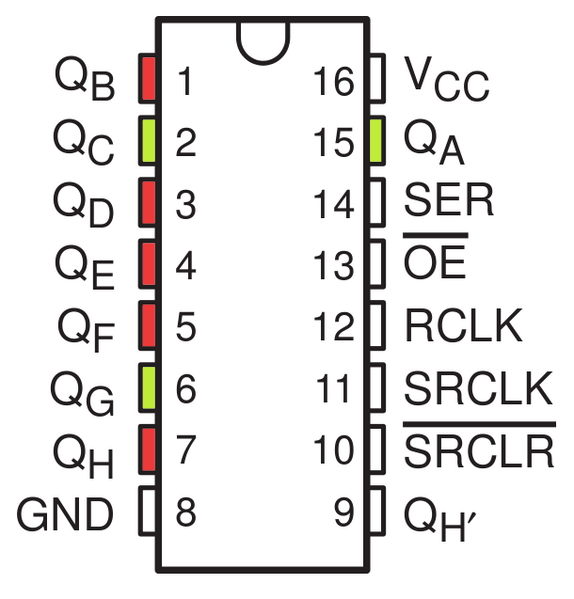
This means that the right most bit that we specify maps to QH, and the left most bit maps to QA. An output is considered active when the bit mapped to it is set to 1. It is important to remember this, as otherwise you will have a very hard time knowing which pins you are using!
Now that we have a basic understanding of how we use bit shifting to specify which pins to use, we can begin hooking it up to our Arduino!
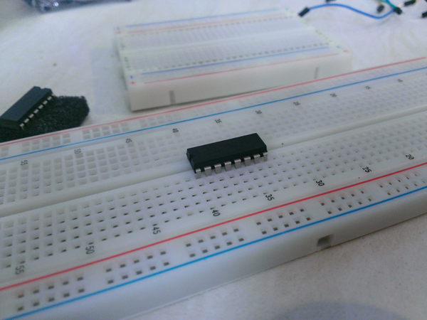
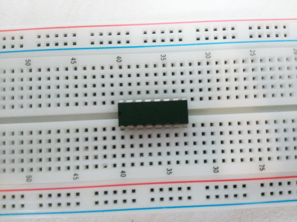
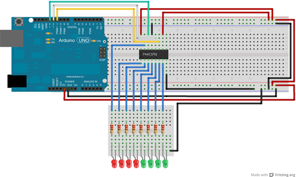
Start by placing the shift register on to your breadboard, ensuring each side of the IC is on a separate side of the breadboard, as per below.
With the notch facing upwards, the pins are 1-8 down the left hand side from top to bottom and 16 – 9 down the right hand side from top to bottom as can be seen in the illustration below.
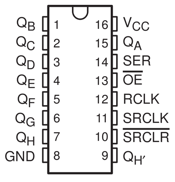
To start with let’s connect pins 16 (VCC) and 10 (SRCLR) to the 5v pin on the Arduino and connect pins 8 (GND) and 13 (OE) to the Gnd pin on the Arduino. Pin 13 (OE) is used to enable the outputs, as this is an active low pin we can just connect this directly to ground.
Next we need to connect the three pins that we will control the shift register with:
- Pin 11 (SRCLK) of the shift register to pin 11 on the Arduino – this will be referred to as the “clock pin”
- Pin 12 (RCLK) of the shift register to pin 12 on the Arduino – this will be referred to as the “latch pin”
- Pin 14 (SER) of the shift register to pin 13 on the Arduino – this will be referred to as the “data pin”
All three of these pins are used in order to do the bit shifting that was mentioned earlier in this guide. Thankfully Arduino provide a helper function specifically for shift registers called shiftOut, which will handle pretty much everything for us; but we’ll get back to that when reviewing the code!
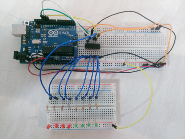
Now, we just have to connect up all of the output pins to our LEDs, ensuring that a resistor is placed before the LEDs as to reduce the current and that the cathodes of the LEDs go back to ground. For the sake of keeping cable density to a minimum, I placed my resistors and LEDs on a separate breadboard however if you’re happy to use the one breadboard you can.
When placing the LEDs be sure that they are connected in order, so that QA is wired to the first LED, and QH is wired to the last LED, as otherwise our code is not going to light up the LEDs in the correct order!
When you’re done you should have something that looks similar to the illustration and photo below.
Now we’re ready to put some code behind it! Plug your Arduino into your computer and upload the following sketch to it:
int latchPin = 12;
int clockPin = 11;
int dataPin = 13;
byte leds = 0;
int currentLED = 0;

void setup()
{
    pinMode(latchPin, OUTPUT);
    pinMode(dataPin, OUTPUT);
    pinMode(clockPin, OUTPUT);

    leds = 0;
}

void loop()
{
    leds = 0;

    if (currentLED == 7)
    {
        currentLED = 0;
    }
    else
    {
        currentLED++;
    }

    bitSet(leds, currentLED);

    digitalWrite(latchPin, LOW);
    shiftOut(dataPin, clockPin, LSBFIRST, leds);
    digitalWrite(latchPin, HIGH);

    delay(250);
}
To start with, we define the following at the top of the sketch:
- The location of the latch, clock and data pins
- A byte which will store the bits that indicate to the shift register which outputs to use
- A variable that will keep track of which LED we should be lighting up
In the setup method we simply initialise the pin modes and the leds variable.
In the loop method, we clear the bits in the leds variable at the start of every iteration so that all the bits are set to 0 as we only want to light up one LED at a time. After this we increment or reset the currentLED variable so that we are lighting up the correct LED next.
After these two operations we get to the more important part – the bit shifting. We first start by making a call to the bitSet method. We pass through to the bitSet method the byte that we are storing the bits in, and the currentLED variable.
This method allows us to set individual bits of the byte by specifying its position. For example, if we wanted to manually set the byte to be 10010, we could use the following calls, as the bits we need to set to 1 are the second from the right (which is position 1, as we start at position 0), and the fifth one from the right, which is at position 4:
bitSet(leds, 1);
bitSet(leds, 4);
So, every time we increment the currentLED variable and pass it to the bitSet method, we are setting the bit to the left of the previous one to 1 every time, and thus telling the shift register to activate the output to the left of the previous one.
After setting the bit(s) we write to the latch pin in order to indicate to the shift register that we are about to send it the data. Once we have done this we make a call to the shiftOut method that is provided to us courtesy of Arduino. This method is designed specifically for the purpose of using shift registers, and allows us to simply shift the bits in one call. To do this we pass through the data and clock pins as the first two parameters, we then pass the LSBFIRST constant, which tells the method that the first bit should be the least significant (i.e. the right most bit) and then we pass through the byte containing the bits that we actually want to shift to the shift register.
Once we have completed the bit shifting, we write to the latch pin again (using HIGH this time) to indicate that we have sent all the data. After that write operation is complete, the matching LED will light up and then we just delay for 250 milliseconds before doing it again!
If you’ve completed all these steps correctly you should have something similar to that in the video below. Note: in the video below I used a slightly modified version of this sketch which lights up all the LEDs sequentially, the sketch above will light one at a time.
Something that should be noted going forward is that this particular shift register cannot safely draw a current higher than 70 mA at a time (which is why the guide shows you how to light one LED at a time instead of all of them).
If you are going to need to draw more than this then you should look into something a bit more powerful such as the TPIC6B595. Alternatively, if you are using the shift register for just LED purposes, try some bigger resistors. If a 680 ohm resistor is placed before each LED this should be enough to keep within roughly 20-30% of the maximum current rating and still keep a relatively bright LED.