I recently purchased an Arduino Uno starter kit which included a number of 7 segment LED displays (like the one pictured below), which were some what confusing for someone new to electronics and the Arduino itself.
After a bit of reading and experimentation with said LED displays, I have developed a reusable library that can be used for these components, and others that are made in the same way.
To complete this small tutorial you will need the following:
- An Arduino device with at least ten digital pins
- A double digit common anode 7-segment LED display
- Ten jumper cables
- Two 330 ohm resistors
- Two breadboards or one with two sets of rails
The LED display I am using for this guide (a 5261BS) came with an Arduino starter kit as previously mentioned, which I purchased from 4tronix UK (http://stores.ebay.co.uk/4tronix-UK). The manufacturer seems to be a company called Wahkitsing, who sell the same part On This Website. However, from the research I’ve done, it seems most manufacturers of these components use the same basic approach, and thus this code and guide should be transferable to other dual digit 7-segment displays.
Wiring it up
The first thing we’re going to have to do is obviously wire up the component to the Arduino. Before doing so I’m going to explain how this particular component actually works, so that you have a better understanding of why we’re doing what we are.
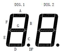
Each digit on the LED display is made up of seven segments, and one extra segment for the decimal point, as can be seen in the illustration below.
The first thing you’re probably wondering is: “how do we use a total of 16 different segments if we only have ten pins on the component?”. The answer to that is by using two pins which act as bit flags to indicate which digit’s segments to light up.
For the component I am using, the digit flags are accessed via pins 8 and 7, however these pins seem to vary between different manufacturers, so be sure to check any instructions that came with yours. Most of these displays ship with a diagram similar to that which can be found below.
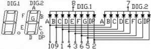
As you can see, the diagram indicates which pins are our digit bit flags (pin 8 for digit 1 and pin 7 for digit 2), and it shows us which pins map to which segment of the digits. In case the diagram is not clear as to which pins map to which segments, they are as follows:
- Pin 10 maps to segment A
- Pin 9 maps to segment B
- Pin 1 maps to segment C
- Pin 4 maps to segment D
- Pin 3 maps to segment E
- Pin 6 maps to segment F
- Pin 5 maps to segment G
- Pin 2 maps to segment DP
Important Note: If your component has illustrations that are different to this it’s important to note which two pins are the bit flags and which map to which segment, as you’ll have to make alterations to the code later to comply with them.
Now that we have an understanding of how the component works, we can begin wiring it up to the Arduino!
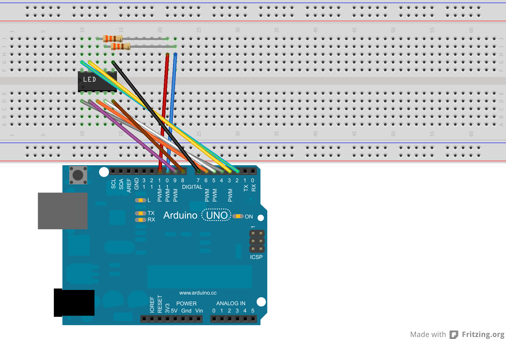
Start by plugging the LED display module into your breadboard, this is going to have to spread over two boards so that you have room to connect all the pins, as can be seen in the picture below.
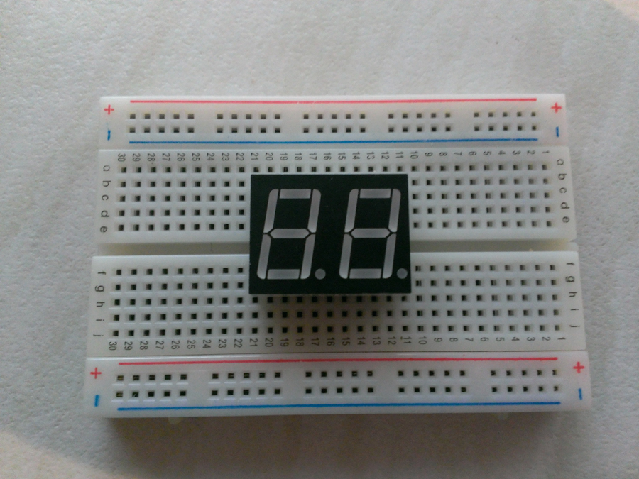
When looking at the component from this perspective (that being so that the decimal points are at the bottom) the pins are in the following order:
- On the bottom side, from left to right: 1, 2, 3, 4, 5
- On the top side, from left to right: 10, 9, 8, 7, 6
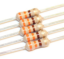
The majority of these pins connect directly to the Arduino itself. However, the two pins mentioned earlier which act as bit flags need to connect through 330 ohm resistors. If you’re not sure how to identify what type of resistor you have, I’d recommend bookmarking This Page. To save you the time in reading though, the resistor you need is the one with two orange bands and a black band, in that specific order, as can be seen below (or if you only have resistors with two orange bands and a brown band this will also suffice).
Once the resistors are connected to pins 7 and 8, place a jumper cable from them to form the following connections:
- Pin 7 of the component to Arduino pin 10
- Pin 8 of the component to Arduino pin 11
The rest of the pins as previously mentioned connect without the need of a resistor, and should be done so as follows:
- Pin 10 of the component to Arduino pin 2
- Pin 9 of the component to Arduino pin 3
- Pin 1 of the component to Arduino pin 4
- Pin 4 of the component to Arduino pin 5
- Pin 3 of the component to Arduino pin 6
- Pin 6 of the component to Arduino pin 7
- Pin 5 of the component to Arduino pin 8
- Pin 2 of the component to Arduino pin 9
An illustration and schematic of this wiring can be found below.
Writing the code
In order to make this easier for those who may not have the strongest of programming abilities, I have written a reusable library which will handle near all of the code side of things for you! To use this library first download it by clicking this link: LEDDisplay Arduino Library or by grabbing the latest source code from This GitHub Repository.
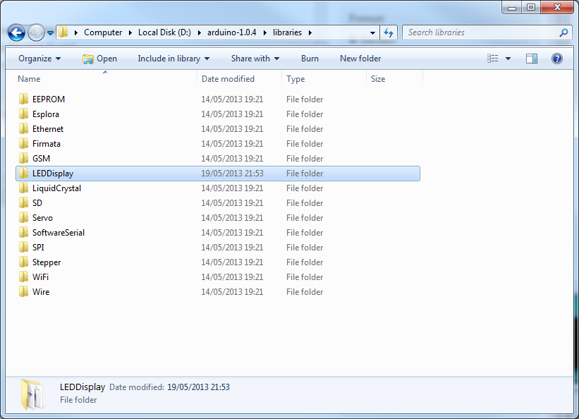
Once you have downloaded the library, extract the LEDDisplay directory into the libraries directory inside your Arduino directory, as can be seen below. Or if you’re using OS X, follow this guide: http://blog.arduino.cc/2009/08/15/new-library-folder-and-compilation-process-in-arduino-0017/
Now that the library is installed, start up the Arduino IDE and copy and paste the following code into it:
#include <LEDDisplay.h>

LEDDisplay *led;

void setup()
{
    int digitFlagPins[] = {10, 11};
    int segmentPins[] = {2, 3, 4, 5 ,6 ,7 ,8, 9};
    int decimalPointPin = 9;
    led = new LEDDisplay(2, digitFlagPins, segmentPins, decimalPointPin);
}

void loop()
{
    led->displayNumber(2, 1);
    led->displayNumber(4, 0);
}
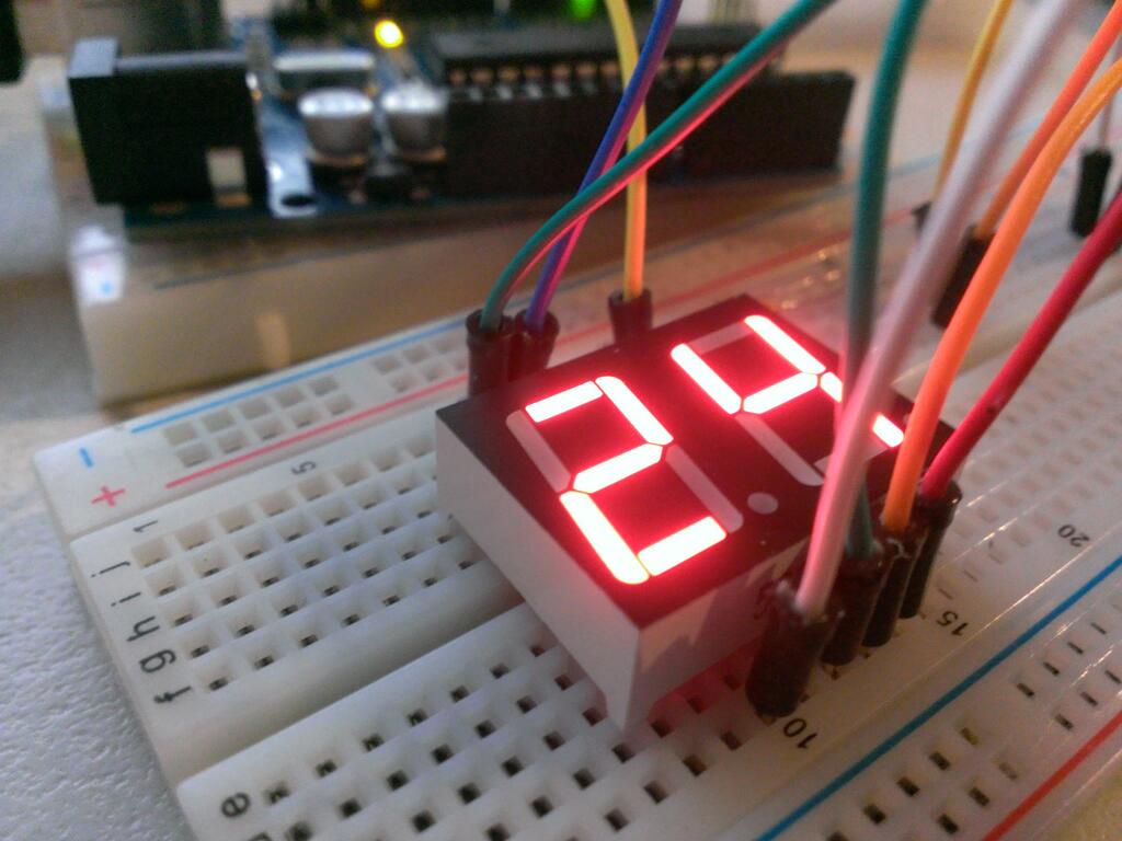
As you can see, this is a very simple example which will show the number “24″ on the LED display (yes, I’ve chosen that number because I love the TV series, 24!); but to explain what it’s doing anyway:
- We start by importing the LEDDisplay library into our sketch by using the #import syntax
- We create an LEDDisplay object that we can then use throughout the sketch
- We instantiate the object inside the setup method (more about this further down)
- We call the displayNumber method of the object to show the number 2 on digit 1, and the number 4 on digit 0 (we count the digits from right to left, so the right most one is zero)
The most daunting part of this code is the code in the setup method which creates the LEDDisplay object. Remember I mentioned earlier about taking note of the pins you connect? Well this is why!
The digitFlagPins array that we find on the first line of the setup method is creating an array of integers with the values 10 and 11. These are the Arduino pin numbers that we have connected to the pins that act as our digit bit flags (the ones that we put through the resistors). It is important that you specify these in the correct order (that being the right most digit be first, so in this case pin 11, as that is connected to the pin that controls the right most digit), otherwise the library will not be able to display the numbers on the correct digits!
The second array we see being initialised is the segmentPins array. This is an array of all the Arduino pin numbers which are connected to pins on the LED display which control the segments; so in this case these are the ones that we connected directly from the breadboard to the Arduino. These also have to be put in the correct order as the library assumes that the pins are in the following order: A, B, C, D, E, F, G, DP.
The third variable we assign to is the decimalPointPin integer, this is simply the Arduino pin number that the decimal point segment is connected to; so in this case pin 9.
After creating these variables, we then pass them in to the LEDDisplay constructor, as well as an additional integer at the beginning, that being the number two. This number indicates to the LEDDisplay object how many digits you have on your display. A maximum of four digits are supported by this library, however as we are using a dual digit display, we simply just pass the number two.
Now, upload this sketch to your Arduino and you should see the number 24 on the display!
To see this in a slightly more dynamic example, we can adapt the example to make the LED display act as a counter (obviously only up to the number 99). To give this a try, copy and paste the following code and upload it to your Arduino:
#include <LEDDisplay.h>

LEDDisplay *led;
int millisecondsPerCount;
int counter;
unsigned long lastUpdate;

void setup()
{
    millisecondsPerCount = 1000;
    int digitFlagPins[] = {10, 11};
    int segmentPins[] = {2, 3, 4, 5 ,6 ,7 ,8, 9};
    int decimalPointPin = 9;
    led = new LEDDisplay(2, digitFlagPins, segmentPins, decimalPointPin);
}

void loop()
{
    unsigned long now = millis();
    if (now - lastUpdate > millisecondsPerCount)
    {
        lastUpdate = now;
        counter++;
        if (counter == 100)
        {
            counter = 0;
        }
    }

    int number = counter;
    for(int i = 0; i < 2; i++)
    {
        led->displayNumber(number % 10, i);
        delay(2);
        number = number / 10;
    }
}
Once uploaded and running, you should see something to the effect demonstrated in the video below:
In addition to the displayNumber method, you can also call the following methods on the LEDDisplay object:
displayDecimalPoint(int digit)– this will light up the decimal point for the digit you pass through to it (again, using 0 as the right most digit)clearDisplay()– this will as the name suggests clear the display