When it comes to creating a more permanent solution for your Arduino prototypes, there’s a good chance that you’ll be looking to reduce the amount of physical real estate being used; enter the ATTiny microcontroller.
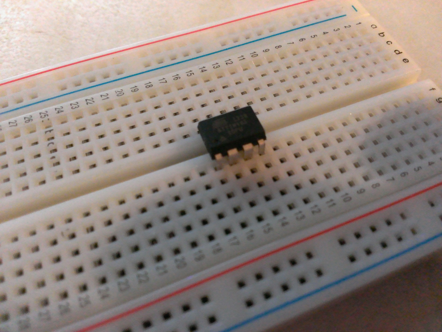
As you can see, the ATTiny takes up considerably less amount of space than having a full sized Arduino. As you’d expect, there is a trade off for it being so small; that being that there are less pins available.
On the ATTiny85 and ATTiny45, we have a total of five pins that we can use as input or output pins, as per the below illustration:
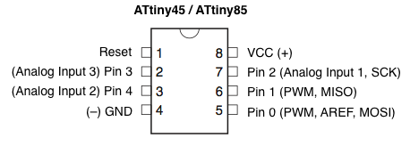
One thing that is worth noting right now: the pin numbers in the labels of the above illustration are the numbers you should use when writing your code. For example, pin 5 of the ATTiny is actually accessed by using pin 0 in your Arduino code, pin 6 of the ATTiny is Arduino pin 1 etc.
Programming an ATTiny
In order for us to upload sketches to the ATTiny, we need to create what is known as a programmer. If you want to, you can purchase ready made ATTiny programmers from a number of places online; but where would be the fun in that!?
Before we can begin, there are a few extra files you need to add to your Arduino IDE.
Setting up our environment
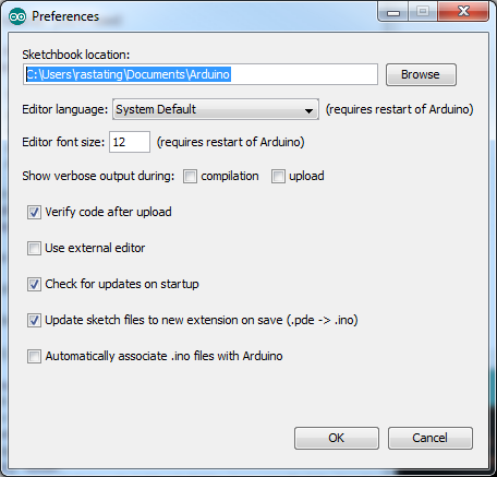
The first thing we need to do is find out where your sketchbook folder is located. To do this, open up the Arduino IDE and open up the preferences window (in Windows this can be done by clicking File > Preferences), the sketchbook location should be the first setting you see at the top of the window:
Inside the Sketchbook location should be a folder called “hardware”; if one doesn’t exist then create it now.
Now that we have the location of your Sketchbook, close the Arduino IDE and Download This ZIP File. Once the download is complete, unzip the contents into the hardware folder that we just created / located.
Your IDE is now setup and ready to program the ATTiny!
Setting up the Arduino as an ISP
The next step we need to take is to turn our Arduino into an ISP (an in-system programmer). As you will have noticed, the ATTiny offers nothing in way of connecting it to your computer, which is why we need to use the Arduino to flash the ATTiny for us with the sketch we want to run on it.
TO do this, simply open the ArduinoISP example (this can be found by clicking File > Examples > ArduinoISP) and then upload the sketch to your Arduino.
This step must be done before you complete the wiring in the next step.
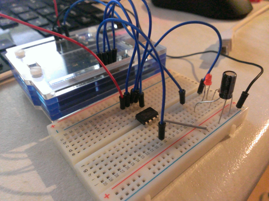
Wiring up the ATTiny programmer
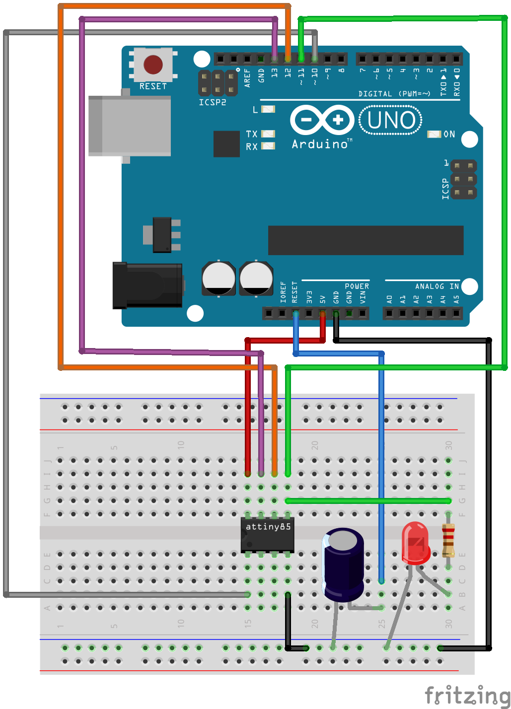
There isn’t much to wiring up this prototype, but something you must remember is that you cannot change the pins that are used on the Arduino - you must use pins 10-13 as per the below; there is no way to change it.
So, wire up your ATTiny as follows:
- Arduino 5v to ATTiny pin 8
- Arduino GND to ATTiny pin 4
- Arduino pin 10 to ATTiny pin 1
- Arduino pin 11 to ATTiny pin 5
- Arduino pin 12 to ATTiny pin 6
- Arduino pin 13 to ATTiny pin 7
In addition to this, we also need to place a 10uF capacitor in between the Arduino reset and GND pins. There have been some reports of this circuit working without the capacitor, but most people will tell you it is required, so we’ll go ahead and do it.
An optional connection, but one you should do for the sake of testing our end product is to connect an LED via a 220ohm resistor to ATTiny pin 5. If you don’t want to test the sketch we will upload to the ATTiny using this circuit, you can skip this.
Your circuit should now look something like this:
Uploading a sketch to the ATTiny
Before uploading sketches to the ATTiny, we first must burn the bootloader; this is much simpler than it sounds.
Go to Tools > Board and select the ATTiny85 (internal 8MHz clock) option and then select the “Arduino as ISP” option in the Tools > Programmer menu.
Next, go to Tools and click the “Burn Bootloader” menu item and you’re done.
Now that our wiring is done and our environment setup, we can now upload sketches to the ATTiny! Go ahead and load up the blink example and change the led variable to 0 instead of 13.
Your sketch should look like this:
int led = 0;

// the setup routine runs once when you press reset:
void setup() {
  // initialize the digital pin as an output.
  pinMode(led, OUTPUT);
}

// the loop routine runs over and over again forever:
void loop() {
  digitalWrite(led, HIGH);   // turn the LED on (HIGH is the voltage level)
  delay(1000);               // wait for a second
  digitalWrite(led, LOW);    // turn the LED off by making the voltage LOW
  delay(1000);               // wait for a second
}
Click upload and if you wired in the LED to the circuit as shown previously it will now blink on and off every second as in the video below:
Additional modifications
If you want to add on to the circuit a bit further, you can wire LEDs up to the following pins in order to receive feedback as to the progress when uploading sketches:
- Arduino pin 9 - the heartbeat LED - pulsates to indicate that the programmer circuit has power
- Arduino pin 8 - the error LED - lights up if an error occurs when uploading a sketch or burning a bootloader
- Arduino pin 7 - the programming LED - flashes as writing to the ATTiny
Below is a video of these extra LEDs with the entire circuit soldered to a piece of veroboard.