Over the past few days I decided to take a step back from hacking together stuff with the Arduino and to instead take the time to read up more on the fundamentals of electronics that I imagined everyone should be aware of; that being how voltage, current and resistance work in a circuit.
If you’re new to electronics, like myself, this may be a rather daunting thing to understand, but hopefully this introduction will clear up any confusion and provide you with the required knowledge.
Why do we need to know about voltage, current and resistance?
The answer to this question is – because these are the factors which allow the electricity to move through a circuit.
Electricity is delivered through a circuit by the movement of free electrons and like most things that move, there has to be a force which makes it move. In terms of electronics, this force is known as the voltage.
The result of applying that force to the electrons is that they begin to move. The number of which pass through a specific point per second is the effect of the force being applied, which we refer to as the current.
Anything in the circuit which limits how many electrons can pass through (i.e. resistors) is known as resistance. (hopefully that one is rather self explanatory!)
There is more to these three components than just this, but to summarise:
- Voltage is the force which moves the electrons
- Current is the the number of electrons that move through a specific point per second
- Resistance restricts the flow of electrons
If voltage is the force which moves the electrons, why can’t we use that to determine the speed?
This is a point I was dwelling on for quite some time. I kept wanting to know why, if a higher voltage meant the electrons would move faster, that we needed to know the current as well, as surely one would be directly proportional to the other, right? Wrong!
When discussing this topic with a friend of mine, he used an analogy which I found very useful in understanding the answer to this question; that being comparing it to moving a box.
If we have a box that we want to push to a different room to the one it is in, there are two factors which define how fast it will get there:
- How hard we push the box - voltage
- Friction on the carpet, gravity (i.e. if pushing up a set of stairs), the weight of the box itself - resistance
If we have a box on wooden polished flooring, we will be able to move it faster than if we have a box on a carpet (which has more friction, or resistance), despite pushing it with the same force (voltage).
As resistance will always determine how fast we can move the boxes, it becomes impossible for us to determine how fast we will move them purely on the amount of force we put behind it. Which brings us to Ohm’s law!
Who is Ohm and what is this law of his!?
Ohm is Georg Ohm, a German physicist who in 1827 published an equation which would allow people to calculate the voltage, current and resistance between two points in a circuit by having any two of the given elements. This equation would later go on to be known as “Ohm’s law”.
Before explaining the equation, we should take note of the units in which we measure voltage, current and resistance:
- We measure voltage (the symbol for which is either E or V) in volts
- We measure the current (the symbol for which is I) in amperes (often referred to as amps), which is abbreviated as A
- We measure the resistance (the symbol for which is R) in ohms, which is abbreviated using the ohms symbol - Ω
The equation uses all three of these measurements, and is as follows:
Voltage (E) = Current (I) * Resistance (R)
As mentioned earlier (and I can’t put enough emphasis on this), this equation allows you to calculate the voltage, current or resistance between two points in the circuit. Without knowing the point at which you begin to measure and the point at which you are stopping, this cannot be applied.
In order to explain and illustrate how Ohm’s law works and how current and voltage is affected in different types of circuits, I am going to use a free online tool called Circuit Lab (https://www.circuitlab.com/). I can’t express how useful this tool is when it comes to experimenting with this calculation and sketching out circuit ideas. It allows for you to create a circuit in the online editor and see what the voltage and current is at any given point in the circuit (essentially simulating the functionality of a Multimeter). It is capable of much more than just this, however for the purpose of this topic it’s the main feature we are interested in!
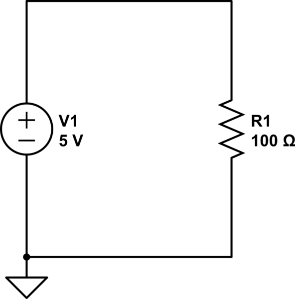
Example 1 – One Resistor
Below we have a simple circuit (Click Here to View on CircuitLab) which consists of a 5 V power source and a 100 ohm resistor. To find out the current between the power source and the resistor we use Ohm’s law, that being I = V / R, or in terms of this circuit 0.05 = 5 / 100, meaning that the current is a total of 50 milliamps (abbreviated as mA).
If you want to view this interactively click the link above to view the circuit on CircuitLab and click Run > DC Simulation, in the panel to the top left you will see the current and voltage. To view the voltage and current at other points in the circuit simply just click on the points to view them in the expression window.
Example 2 – Two Resistors
In this example we will expand on example 1 and add a second resistor so that we can see how the voltage drops if we measure it after the first resistor. To access this example on CircuitLab, Click This Link.
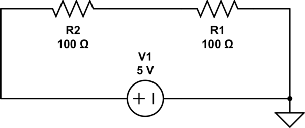
In example 1, we had 100 ohms of resistance which resulted in a current of 50 mA. In this example we have a total of 200 ohms of resistance, and thus our current is halved to 25 mA. As with the previous example, the voltage just before resistor R2 is 5v, however if we look at the voltage after it (i.e. between R2 and R1) we see that the voltage has dropped to 2.5v.
It’s important to remember, in a series circuit like the one above, the current will be the same throughout the entire circuit and the only change we see is in the voltage. In parallel circuits the opposite happens, and the current is split as opposed to the voltage.
Example 3 – Two Resistors in a Parallel Circuit
As mentioned in the previous paragraph, in parallel circuits the current is split between the numerous branches, with the most current going to those with the least resistance. In the example below (which can be viewed on CircuitLab Here) we have two resistors in parallel, one at 200 ohms and one at 100 ohms.
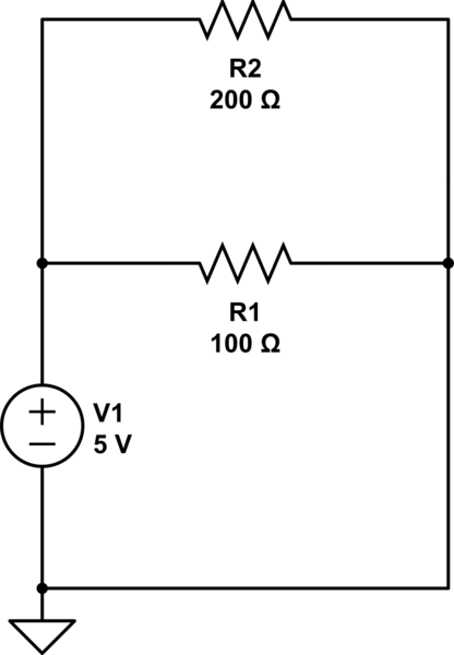
In the middle branch that contains resistor R1 we will have a current of 50 mA (5 V / 100 ohms = 50 mA) and on the top branch which contains resistor R2 we will have a current of 25 mA (5 V / 200 ohms = 25 mA).
To summarise…
These are the points that you should be taking away from reading this:
- Voltage is the force which pushes free electrons through a circuit
- Current is the number of free electrons that move through a circuit per second
- Resistance restricts the movement of electrons
- In series circuits the current remains the same but the voltage can fluctuate
- In parallel circuits the voltage remains the same but the current is split amongst the different “branches”
I’d also recommend bookmarking This Calculator. Although the maths behind Ohm’s law isn’t particularly complicated, it just quickens things up and reduces the mistakes you can potentially make!